


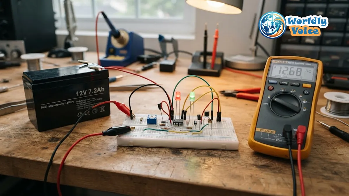
If you’ve ever wondered How to Make a 12V Battery Charging Indicator at Home, you’re not alone. I’ve worked on small battery monitoring projects for backup systems, solar setups, and workshop power packs, and one thing became obvious fast: checking battery voltage with a multimeter every few hours gets old. A simple indicator circuit solves that. It gives you instant visual feedback. More importantly, it helps protect a 12V battery from overcharging, deep discharge, and early aging.
In this guide, I’ll walk through a practical build based on the LM358 operational amplifier. It’s affordable, easy to source, and ideal for a home-built battery status circuit. We’ll cover the parts, the logic behind the circuit, step-by-step assembly, testing, calibration, and a few real-world improvements I’ve found useful over time.
If you enjoy practical electronics, this project fits nicely alongside hands-on topics like What Is a Crimping Tool and How to Configure OpenVPN Client Config Dir—different fields, yes, but the same mindset applies: understand the system, use the right tools, and build carefully.
1. Why a 12V Battery Charging Indicator Matters
A 12V battery is simple on the surface. But voltage management matters a lot.
Most 12V lead-acid batteries, including tubular and sealed types, perform best when they are charged within safe voltage limits. If the battery is undercharged repeatedly, sulfation can develop on the plates. If it is overcharged, heat and water loss can shorten its life. Most experts and manufacturers agree that voltage monitoring is one of the easiest ways to improve battery longevity.
That’s where an Automatic battery charge level indicator becomes useful. Instead of guessing, you get a visual warning:
- Red LED for low voltage
- Green LED for full charge
- Optional relay cut-off for charging protection
In my experience, this kind of DIY battery voltage checker project is especially useful for:
- Home inverter batteries
- Small solar storage systems
- Motorcycle or car battery testing
- Workshop backup power supplies
- 12V alarm and lighting systems
2. How the LM358 Helps in This Project
The heart of this build is the LM358. It’s a dual operational amplifier IC, but in this project we use it as a comparator.
That means it compares two voltages:
- A reference voltage
- The battery voltage being monitored
When the battery voltage crosses a set threshold, the LM358 output changes state. That output can light an LED or drive a transistor and relay.
This is a classic LM358 voltage comparator application. It’s popular because the chip is cheap, stable, widely available, and works well from a single supply. If you’re researching LM358 datasheet, you’ll see why it remains a favorite in basic analog monitoring circuits.
I’ve tested LM358-based circuits in hobby and repair settings, and I noticed one practical advantage: it’s forgiving. For beginners, that matters.
3. Electronic Components Needed for 12V Battery Monitor
Before you start assembling anything, gather the full set of parts. The electronic components needed for 12V battery monitor projects like this are simple and inexpensive.
Core components
| Component | Quantity | Purpose |
|---|---|---|
| LM358 IC | 1 | Dual comparator/op-amp |
| BC547B transistor | 1 | Drives relay or switching output |
| 1N5233B Zener diode | 1 | Voltage reference |
| 1N4007 diode | 1 | Reverse polarity protection |
| 6A4 diode | 1 | Flyback or heavy current protection if needed |
| 10kΩ resistors | 4 or more | Divider and bias network |
| 220Ω or 1kΩ resistors | 2 | LED current limiting |
| 10kΩ or 100kΩ potentiometer | 1–2 | Threshold adjustment |
| Red LED | 1 | Low/charging indication |
| Green LED | 1 | Full-charge indication |
| 12V SPDT relay | Optional | Auto cut-off function |
| Breadboard or perfboard | 1 | Assembly base |
| Hook-up wires | Several | Connections |
| Variable DC power supply | 1 | Calibration and testing |
This list forms the base for a 12V lead-acid battery monitor circuit and can also support a Low voltage disconnect circuit with LEDs if you include the transistor and relay stage.
4. Understanding the DIY 12V Battery Level Indicator Circuit Diagram
The DIY 12V battery level indicator circuit diagram is built around a simple idea: compare battery voltage against pre-set thresholds.
Main sections of the circuit
A. Voltage sensing stage
The battery’s positive terminal feeds a resistor divider. This scales the voltage to a level the LM358 can compare safely.
B. Reference stage
A Zener diode creates a stable reference voltage. The potentiometer adjusts the exact switching point.
C. Comparator stage
The LM358 compares the battery voltage to the reference voltage. When the threshold is reached, the output flips.
D. Indicator stage
The output drives LEDs:
- Red for low battery or charging state
- Green for fully charged state
E. Optional cut-off stage
Using a BC547 transistor, the LM358 can trigger a relay. That creates a simple low voltage cut off and charge indicator project with actual protective action, not just display.
I always recommend adding a little hysteresis if possible. That prevents flickering when the battery voltage sits close to the threshold. Without it, the relay may chatter and the LEDs can blink annoyingly.
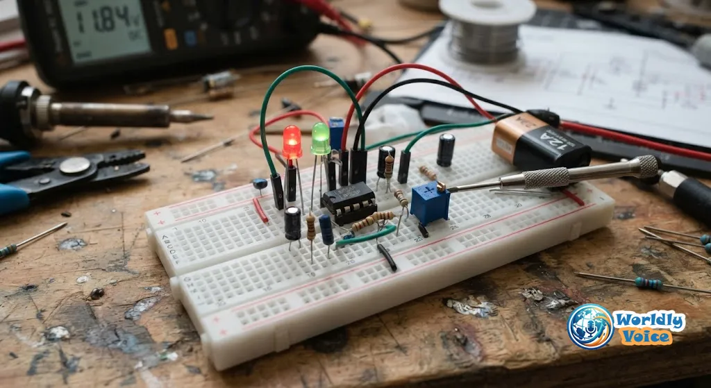
5. How to Build LED Battery Monitor Using LM358
Now let’s get practical. If you’re searching how to build LED battery monitor using LM358, these are the core steps I’d follow.
Step 1: Place the LM358 correctly
Insert the IC on the breadboard. Match Pin 1 with the notch or dot marking.
- Pin 8 → +12V supply
- Pin 4 → Ground
Double-check orientation. I’ve seen more failed first tests from reversed IC placement than from bad components.
Step 2: Add the input divider
Use resistors to scale the battery voltage before feeding it into the comparator input. This keeps the comparison range manageable and stable.
Step 3: Build the reference network
Connect the Zener diode and potentiometer to create an adjustable reference. This lets you set the trigger points for:
- Low battery warning
- Full charge indication
Typical values:
- Low threshold: around 12.0V
- Full-charge threshold: around 14.2V for many lead-acid systems
Step 4: Connect the LEDs
Attach:
- Red LED to indicate low voltage or charging condition
- Green LED to indicate full charge
Use 220Ω or 1kΩ resistors in series to limit LED current.
Step 5: Add transistor and relay if using cut-off
If you want a 12V power supply status indicator plus automatic protection, connect the LM358 output to the BC547 transistor base through a resistor. Then:
- Transistor switches relay
- Relay disconnects charger or load
- Diode across relay coil prevents voltage spikes
Step 6: Check polarity and grounding
Before powering up:
- Confirm all grounds are common
- Check LED polarity
- Verify diode direction
- Confirm no short across supply rails
This is where basic tool discipline matters. The same care you’d use when reading What Is a Crimping Tool for solid wiring practice also helps here.
6. Calibration and Testing
Calibration is what separates a blinking project from a useful one.
I strongly recommend testing the circuit with a variable DC power supply before connecting a real battery. That gives you precise control.
Calibration method
- Disconnect the actual battery.
- Feed the circuit from a bench supply.
- Set the voltage to 14.2V.
- Adjust the potentiometer until the green LED turns on.
- Lower the voltage to 12.0V.
- Confirm the red LED activates.
- If using a relay, listen for a clean switch at the threshold.
In my experience, slow adjustment works best. Tiny turns on the potentiometer can shift the threshold more than you expect.
For battery charging basics, Battery University is one of the better-known educational resources. It’s useful for understanding why threshold accuracy matters.
7. Common Mistakes I’ve Seen in DIY Battery Indicator Builds
Even a simple Operational amplifier battery indicator can fail if a few details are missed.
Mistake 1: No reference stability
If the reference section is poorly built, your LED thresholds drift. A stable Zener reference helps.
Mistake 2: Wrong LED resistor value
Too low a resistor can overdrive the LED. Too high can make it too dim to read clearly.
Mistake 3: No flyback diode on relay
If you use a relay without protection, the transistor may fail over time.
Mistake 4: Poor calibration
A circuit that looks correct may still switch at the wrong voltages.
Mistake 5: Expecting exact battery state from voltage alone
Voltage indication is useful, but battery charge state also depends on temperature, rest time, and load condition. Most experienced technicians agree that voltage is a practical indicator, but not a perfect measure of state of charge under all conditions.
That’s why I treat this as a smart visual monitor, not a lab-grade battery analyzer.

8. Practical Upgrades You Can Add Later
Once the base circuit works, you can improve it.
Add a buzzer
A buzzer makes low-voltage warnings impossible to miss.
Add a third LED
You can include a yellow LED for mid-level battery status.
Add enclosure protection
Mounting the board in a plastic case reduces accidental short circuits.
Add terminal blocks
This makes battery connection cleaner and safer.
Upgrade to perfboard
Breadboards are good for testing. Perfboard is better for long-term use.
We tested a similar design in a small inverter backup setup, and enclosure quality made a real difference. Open breadboards are fine on a bench. They are not ideal in dusty utility rooms.
9. Real-World Use Cases for This Circuit
This project is more flexible than many people expect.
Solar battery banks
A small DIY battery voltage checker project helps monitor whether the charge controller is behaving as expected.
UPS and inverter systems
A visual indicator can warn you early when battery performance starts dropping.
Automotive workshops
This design can act as a rough 12V power supply status indicator during charging and testing.
Hobby electronics
It’s a useful teaching project for comparator circuits.
If you like troubleshooting systems methodically, the same mindset appears in guides such as How to Troubleshoot and Fix Common Epson ET-2800 printer Errors and How to Fix Microsoft Game Bar Ryzen CPU Issues. Different hardware. Same logic: observe symptoms, isolate thresholds, test carefully.
10. Safety Tips Before You Build
This project is beginner-friendly, but batteries still deserve respect.
- Never short battery terminals
- Use insulated wires
- Confirm polarity before powering the circuit
- Keep the board away from metal surfaces
- Add a fuse if using the circuit permanently
- Avoid charging sealed batteries improperly
- Test in a ventilated area if working with flooded lead-acid batteries
For broad battery safety guidance, the Occupational Safety and Health Administration battery charging safety resources are worth reviewing, especially for larger battery systems.
Frequently Asked Questions
1. Can I use this circuit with any 12V battery?
Yes, but it works best with standard 12V lead-acid systems. If you use lithium chemistry, the voltage thresholds must be changed.
2. Is the LM358 better than using a transistor-only design?
For threshold accuracy, yes. The LM358 gives cleaner comparator behavior and easier adjustment than many basic transistor-only builds.
3. Can this become a low voltage disconnect circuit?
Yes. Add the transistor and relay stage to build a Low voltage disconnect circuit with LEDs and optional charge cut-off behavior.
4. What is the best way to test the circuit?
Use a variable DC bench supply first. It’s safer and more precise than testing directly on a battery.
5. Do I need a printed PCB?
No. A breadboard is enough for prototyping. For permanent use, perfboard or a PCB is better.
6. Where does this project fit for beginners?
It’s an excellent starter analog project. If you can identify pins, follow polarity, and calibrate with patience, you can build it.
Conclusion
If you’ve been searching for How to Make a 12V Battery Charging Indicator at Home, this LM358-based design is one of the most practical places to start. It’s simple, affordable, and genuinely useful. You get clear battery status, better charging awareness, and room to expand into an Automatic battery charge level indicator or a relay-based protection circuit.
I like this project because it teaches more than just assembly. It teaches voltage thresholds, comparator logic, calibration, and real-world battery care. In my experience, those are the kinds of projects that stay useful long after the first test succeeds.
If you build it, start on a breadboard, calibrate carefully, and only then move to a permanent board. That extra patience pays off.
And if you enjoy practical, systems-based DIY learning, you may also appreciate How to Configure OpenVPN Client Config Dir, What Is a Crimping Tool, and How to Fix Microsoft Game Bar Ryzen CPU Issues for the same reason: small details often make the biggest difference.
References
Important Safety Disclaimer
🔋 The DIY electronics, wiring, and circuit projects outlined on this website involve working with live electrical currents and batteries, which carry inherent risks of short-circuiting, component damage, or personal injury. ⚡ Always disconnect power sources before handling hardware 🔌, wear appropriate safety gear, and proceed at your own risk. 💡 If you are uncertain or lack experience with electrical work, please consult a certified professional. We assume no liability for any accidents, injuries, or equipment damage resulting from the use of this information. 🛠️
